Amazon Web Services (AWS)
Amazon Web Services (AWS)- SAP on AWS (Collection of resources)
- Obtain meta data about the instance you are running on
- EC2 compute instances, prices, specs etc. (non AWS web site)
- Public data Sets hosted by AWS
- EC2 User Guide for Linux
- Reachability of all AWS CIDDR blocks (Has my ISP a routing problem?)
- 10811 views
AWS Architect Certification (Associate & Professsional)
AWS Architect Certification (Associate & Professsional)Associate Certification
- AWS landing page: AWS Certified Solutions Architect – Associate
- 80 minutes multiple choice test
- Recommended trainings
- Sample questions
- AWS Practice Exam Questions (IaaS Academy)
Resource Collection
| Topic | Resources | White Papers | Technical Terms | Qwiklabs |
|---|---|---|---|---|
|
EC2
|
Introduction to EC2 Spot Instances: 20 minutes |
|||
| ELB | ELB: Documentation | sticky session, ELB, ALB, NLB, code 504, TCP/IP Level 7, TCP/IP level 4, intelligent routing, Cross Zone Load Balancing, Path Patterns | Working with Elastic Load Balancing: 20 minutes | |
| Networking: VPC | End point, gateway, public subnet, subnet, peering, routing, AZ | |||
| Networking: Direct Connect | FAQs |
VLAN, 1000BASE-LX, 10GBASE-LR, singlemode fiber, Bidirectional Forwarding Detection, IPsec VPN, Border Gateway Protocol (BGP), Autonomous System Number (ASN) |
||
| Storage: EBS | EC2 FAQs | |||
| Storage: S3, CloudFront | Bucket, Origin Access Identity, trusted signer, Cloud Front signed URL | |||
| Storage: Glacier | FAQs | vault lock policy | ||
| Storage: Storage Gateway | FAQs | Youtube Introduction video | Gateway-VTL, Gateway-Cached Volumes, Gateway-Stored Volumes | |
| SQS | FAQ (one question) | hidden (after having fetched it), standard queue, FIFO queue, batch, send receive, delete, DeadLetterSourceQueues, Lifecycle, long polls, retention | ||
| Security |
Overview of Security Processes Introduction to AWS Security (High level introduction) |
IDS (Re-Invent pres.), DDos, WAF sandwich | Auditing Your Security with AWS Trusted Advisor: 35 minutes Auditing Changes to Amazon EC2 Security Groups: 37 minutes |
|
| Autoscaling |
Example setup (youtube 11min) |
Maintaining High Availability with Auto Scaling: 50 minutes Launching Amazon EC2 Spot Instances with Auto Scaling and Amazon CloudWatch: 45 minutes |
||
| Database: RDS | FAQs | know the DB specific replication technologies RDS is using | Administering Amazon RDS for Microsoft SQL Server: 90 minutes | |
| Database: DynamoDB | FAQs |
partition key, item, attribute, key-value, composite primary keys, Global Secondary Index, Local Secondary Index (LSI), Projection, Fine-Grained Access Control (FGAC), provisioneds through put, cross-region replication, streams |
Working with Amazon DynamoDB:: 25 minutes | |
| Database: Redshift | Getting Started Guide (Video, hands on lab etc.) | Cluster, Node, Cluster Type, Cluster Parameter Group, WLM (Workload management Configuration) | Working with Redshift: 55 minutes | |
| CloudWatch | FAQs | |||
| CloudFormation | Overview of Deployment Options on AWS (Covers as well OpsWork and CodeDeploy | Stack, Template, create- cancel- delete- rollback-stack, UserData, AWS:CloudFormation:init, stack updates | Creating an Amazon Virtual Private Cloud (VPC) with CloudFormation: 27 minutes Launching and Managing a Web Application with AWS CloudFormation: 27 minutes |
|
| Elastic Beanstalk | FAQs Documentation |
ebextensino, leader_only | ||
| Architecure, Availability | RTO, RPO, AZ | |||
| SNS | SNS Mobile Push | topic, subscribe, publish | ||
| SWF: Simple Workflow Service | Developer Guide | asynchronous, distributed, workflow, activities, domain, activity workers, activity tasks, deciders | ||
| Route 53 | DNS, A (address) record, CNAME (canonical name record), AAAA (IPv6 addres record), Alias record, hosted zone, TTL, WWR (Weighted Round Robin), LBR (Latency Based Routing), Geo DNS, private DNS, health check | Introduction to Amazon Route 53: 55 minutes |
Annoying Facts
S3 Path Styles
1. Virtual hosted-style
Format: https://bucket-name.s3.Region.amazonaws.com/key name (Reference)
2. Path-style
support ends September 30, 2020
Examples:
- https://s3.amazonaws.com/jsb-public/classic_amazon_door_desk.png
- https://s3-us-east-2.amazonaws.com/jsb-public/classic_amazon_door_desk…
- http://example-bucket.s3-website.us-west-2.amazonaws.com/photo.jpg
3. C-Name Method
Example: http://www.awsexamplebucket1.net/homepage.html
The C.Name is an alias for bucketname.s3.us-east-1.amazonaws.com (Reference)
4. s3-Region
Example: https://my-bucket.s3-us-west-2.amazonaws.com
some regions only
Professional Certification
AWS landing page: AWS Certified Solutions Architect – Professional
170 minutes: Multiple choice and multiple answer questions
Recommended trainings
- Advanced Architecting on AWS
- Exam Readiness Workshop
General advice
- How I Passed The AWS Solutions Architect Professional Exam (Hydras)
- Passing the AWS Professional Solutions Architect Exam (Identifies important domains)
- AWS Professional Solution Architect Certification Tips
Resource Collection (for specific Professional Certification Topics)
| Topic | Resources | White Papers | Technical Terms | Qwiklabs |
|---|---|---|---|---|
|
Architecture |
Well-Architected Framework (Great appendix) |
Security, Reliability, Performance, Cost optimization | ||
|
IAM |
Cognito, STS, Identity Federation, SSO | |||
|
Deployment: CodeDeploy |
FAQs | configuration, application, revision, group, Appspec file, lifecycle events, agent | Introduction to CodeDeploy: 40 minutes |
|
|
Deployment: CodePipeline |
FAQs | pipeline, revision, stage, artifact, transition, action | ||
|
Architecture: CloudFront |
FAQs | Developer's Guide | edge location, CNAME alias, invalidation requests, price class, geo restriction, RTMP delivery, signed request | |
|
Data Pipeline |
FAQs | Documentation | activity, precondition, on-premises task runner | |
|
Kinesis |
FAQs | Documentation |
Introduction to Amazon Kinesis Firehose: 30 minutes
Building Real-Time Dashboards with Amazon Kinesis Dynamic Aggregators: 55 minutes |
Qwiklabs
- SA Pro Learning Quest: 295 minutes
- General topics which are useful:
- Introduction to AWS Device Farm: 30 minutes
- Introduction to ElasticCache: 25 minutes
- Introduction to Amazon Elasticsearch Service: 30 minutes
- Introduction to Key Management Service: 30 minutes
- Introduction to Lambda: 30 minutes
- Event-driven Programming with Amazon DynamoDB Streams and AWS Lambda: 35 minutes
- Introduction to EC2 Container Service: 30 minutes
- Introduction to Amazon API Gateway: 35 minutes
- Building Search Into Your Applications With CloudSearch: 32 minutes
- Working with AWS OpsWorks: 40 minutes
- Deploy a Java EE Application on AWS Elastic Beanstalk Using Docker Containers: 40 minutes
- Working with Amazon CloudFront for Dynamic Content Acceleration: 60 minutes
- Caching Static Files with Amazon CloudFront: 30 minutes
- Introduction to Amazon Elastic MapReduce (EMR): 30 minutes
- Building Scalable Web Applications with Elastic Beanstalk: 59 minutes
- Enhancing Your Android Application Using AWS Mobile Services: 35 minutes
- 4366 views
AWS CloudFormation (Resource Collection)
AWS CloudFormation (Resource Collection) Stefan Schneider Wed, 02/20/2019 - 10:08- 948 views
Get AMI Ids for all world wide AWS regions
Get AMI Ids for all world wide AWS regionsAWS CloudFormation is a technology which allows automated software installation in all AWS regions.
AWS CloudFormation requires a unique AMI identifier to pick the appropriate AMI. AWS is using however different AMI identifiers for the same content in all regions. A developer who wants the script to work in all regions world wide has to lookup all AMI identifiers for all regions.
The script below automates this task. It takes the AMI name as a parameter. It'll then print the output in a json format of a CloudFormation mapping.
Example
Excute the script as:
$ ./getAMIs.sh suse-sles-12-sp3-byos-v20180104-hvm-ssd-x86_64
The result will be:
Will search for AMIs with name: suse-sles-12-sp3-byos-v20180104-hvm-ssd-x86_64
---------------------------------------
"eu-north-1"	: {"HVM64": "NOT_SUPPORTED" },
"ap-south-1"	: {"HVM64": "ami-0f227660" },
"eu-west-3"	: {"HVM64": "ami-5212a52f" },
"eu-west-2"	: {"HVM64": "ami-c5ccd4a1" },
"eu-west-1"	: {"HVM64": "ami-2aae3953" },
"ap-northeast-3"	: {"HVM64": "ami-4c040a31" },
"ap-northeast-2"	: {"HVM64": "ami-15ff5f7b" },
"ap-northeast-1"	: {"HVM64": "ami-caf26eac" },
"sa-east-1"	: {"HVM64": "ami-aea7e4c2" },
"ca-central-1"	: {"HVM64": "ami-4ed85d2a" },
"ap-southeast-1"	: {"HVM64": "ami-eb6f1997" },
"ap-southeast-2"	: {"HVM64": "ami-b7ec1ed5" },
"eu-central-1"	: {"HVM64": "ami-c40696ab" },
"us-east-1"	: {"HVM64": "ami-be2b7ac4" },
"us-east-2"	: {"HVM64": "ami-8fefc4ea" },
"us-west-1"	: {"HVM64": "ami-a34747c3" },
"us-west-2"	: {"HVM64": "ami-36aa004e" },
Use this output to create a CloudFormation mapping like:
"AWSRegionArch2AMI" : {
    "eu-north-1"     : {"HVM64": "NOT_SUPPORTED"},
    "ap-south-1"     : {"HVM64": "ami-0f227660" },
    "eu-west-3"      : {"HVM64": "ami-5212a52f" },
    "eu-west-2"      : {"HVM64": "ami-c5ccd4a1" },
    "eu-west-1"      : {"HVM64": "ami-2aae3953" },
    "ap-northeast-3" : {"HVM64": "ami-4c040a31" },
    "ap-northeast-2" : {"HVM64": "ami-15ff5f7b" },
    "ap-northeast-1" : {"HVM64": "ami-caf26eac" },
    "sa-east-1"      : {"HVM64": "ami-aea7e4c2" },
    "ca-central-1"   : {"HVM64": "ami-4ed85d2a" },
    "ap-southeast-1" : {"HVM64": "ami-eb6f1997" },
    "ap-southeast-2" : {"HVM64": "ami-b7ec1ed5" },
    "eu-central-1"   : {"HVM64": "ami-c40696ab" },
    "us-east-1"      : {"HVM64": "ami-be2b7ac4" },
    "us-east-2"      : {"HVM64": "ami-8fefc4ea" },
    "us-west-1"      : {"HVM64": "ami-a34747c3" },
    "us-west-2"      : {"HVM64": "ami-36aa004e" }
    }
Important: remove the colon at the last printed line. A short coming of the current script...
The Script
Create a file with a name (like getAMIs.sh):
#!/bin/bash
# This script takes a a parameter which needs to be a name of an AWS AMI
# The string will have to identify the AMI uniquely in all regions.
# The script will then identify the AMI identifier in all common regions (but China)
# The script will generate an output which can be copied into json files of AWS CloudFormation
#
# The script has been tested on Mac OS only
# The script uses the AWS command line tools.
# The AWS command line tools have to have a default profile with the permission to
# describe a region and to describe an image

# The script can be run with normal OS user privileges.
# The script is not supposed to modify anything.
# There is no warranty. Please check the script upfront. You will use it on your own risk
# String to be used when no AMI is available in region
NOAMI="NOT_SUPPORTED"
# Change your aws prfile if needed here:
PROFILE=" --profile default"
# Check whether AWS CLI is installed and in search path
if ! aws_loc="$(type -p "aws")" || [ -z "$aws_loc" ]; then
echo "Error: Script requeres AWS CLI . Install it and retry"
exit 1
fi
# Check whether parameter has been provided
if [ -z "$1" ]
then
NAME=suse-sles-12-sp3-byos-v20180104-hvm-ssd-x86_64
echo "No parameter provided."
else
NAME=$1
fi
echo "Will search for AMIs with name: ${NAME}"
echo "---------------------------------------"
##NAME=suse-sles-12-sp3-byos-v20180104-hvm-ssd-x86_64
R=$(aws ec2 describe-regions --query "Regions[].{Name:RegionName}" --output text ${PROFILE})
for i in $R; do
AMI=`aws ec2 describe-images --output text --region $i --filters "Name=name,Values=${NAME}" ${PROFILE} | awk -F"\t" '{ print $7;}'i`
if [ -z "$AMI" ]
then
AMI=$NOAMI
fi
echo "\"${i}\" : {\"HVM64\": \"${AMI}\" },"
done
The script uses a variable PROFILE which is set to default. Change this variable setting if you need to use a different AWS configuration
The script isn't perfect. Please help improving it. Please post updates as comments to this page if you enhanced it.
Context needed...
This script assumes
- that the AWS CLI is installed on the system.
- that the AWS CLI is configured with a default profile on the system. The user of the default profile will have to have the rights to execute the describe statements.
- that the AMI name provided is an exact match of the name. It will print "NOT_SUPPORTED" entries otherwise
- that it can reach the Internet...
- 3445 views
AWS Command Line Interface (CLI): Best Practises
AWS Command Line Interface (CLI): Best PractisesUse an UTF locale when using AWS CLI on Unix/Linux
There are AWS strings which can be coded in Unicode. These are at least EC2 tags and volume tags.
Unix/Linux scripts which will run as super user will most likely run in the C locale.
The C locale is an ASCII 7 bit locale which doesn't support Unicode characters. The Python run time which gets used by the AWS CLI will throw an error message because it can't convert Unicode characters.
The simplest way to avoid this error is to start any script using AWS CLI with a set locale like:
export LC_ALL=en_US.UTF-8
Here is an example on how to reproduce the error:
MYPROFILE=default
INSTANCE=i-1234567890
REG=us-east-1
echo " I am in locale:"
export LC_ALL=en_US.UTF-8
locale
echo "*******"
aws ec2 create-tags --profile $MYPROFILE --region $REG --resources $INSTANCE --tags Key=Unicodetest,Value=SchöneScheiße
aws --profile $MYPROFILE ec2 describe-instances --region $REG  --instance-ids $INSTANCE
echo "*******"
echo " I am in locale:"
export LC_ALL=C
locale
echo "*******"
aws ec2 create-tags --profile $MYPROFILE --region $REG --resources $INSTANCE --tags Key=Unicodetest,Value=SchöneScheiße
aws --profile $MYPROFILE ec2 describe-instances --region $REG  --instance-ids $INSTANCE
echo "*******"
The error message looks like:
ascii' codec can't decode byte 0xc3 in position 25: ordinal not in range(128)
This error is annoying since administrators may add Unicode strings in their browser at any point of time. Commands like describe-instance which dump all information about an instance are going to fail.
- 5107 views
AWS Platform Identification
AWS Platform IdentificationApplications may want to know whether they run on the AWS platform or not. There are a number of ways to identify whether your application runs on AWS or not. AWS documents a numbre of them as well.
Disclaimer: The stability of the AWS APIs discussed below varies. Please use the references to the AWS documentation to verify whether the stability of the API is sufficient for your use case.
EC2 Instance Metadata Service V1
The hypervisor of any EC instance is providing a range of information which is available to a given EC instance only. The information is provided through a number of web pages which are accessible through http://169.254.169.254. The AWS page "Instance MetaData and User Data" provides more details about the information offered through this service. This service is available independent of the AMIs operating system.
This information can be gathered by any process on any platform without increased (means root) privileges.
EC2 Instance Metadata Service V2
AWS released a version 2 with a bit more security. Please check the online documentation.
AWS Specific HTTP Header Fields of the Instance Meta Service
Each http request against a page of this service is answered with a AWS specific signature in the http response header field. The Server field contains the string EC2ws.
This field is platform independent.
Check this Field on a Linux Platform
One way to verify this field is the Linux curl command:
ec2-user@ip-w-x-y-z:~> curl -I 169.254.169.254 | grep Server
Server: EC2ws
This information can be gathered by any process on any platform without increased (means root) privileges.
Check this Field on the Windows Platform
Open a Power Shell Window with adminstrator rights and enter the following command sequence:
$url = "http://169.254.169.254"
$request = [System.Net.WebRequest]::Create($url)
$request.Method = "HEAD"
$request.Proxy = $null
$response = $request.GetResponse()
$response.Headers.Get("Server")
The last command will display the string EC2ws.
Signed AWS Dynamic Data
Every EC2 instance hosts dynamic instance specific data which got signed by AWS (see AWS Instance MetaData and User Data, section: Dynamic Data Categories).
The document http://169.254.169.254:/latest/dynamic/instance-identity/document hosts a JSON document which looks similar to this one:
{
  "instanceId" : "i-c495bb93",
  "billingProducts" : [ "bp-xxx" ],
  "accountId" : "xxx",
  "imageId" : "ami-e80xxxx",
  "instanceType" : "c3.xlarge",
  "kernelId" : "aki-825ea7eb",
  "ramdiskId" : null,
  "pendingTime" : "2015-02-24T14:38:43Z",
  "architecture" : "x86_64",
  "region" : "us-east-1",
  "version" : "2010-08-31",
  "availabilityZone" : "us-east-1c",
  "privateIp" : "w.x.y.z",
  "devpayProductCodes" : null
}
The authenticity of this document can be verified through the two documents hosted under
- http://169.254.169.254:/latest/dynamic/instance-identity/pkcs7
- http://169.254.169.254:/latest/dynamic/instance-identity/signature
This verification method is operating system independent and it doesn't require a process to have increased access privileges (beyond http access).
AWS BIOS Serial Number
EC2 instances have serial numbers which start with the string ec2.
One way to gather this information on a Linux system is the dmidecode command:
ip-w-x-y-z:/home/ec2-user # dmidecode -s system-serial-number
ec296900-a260-8001-9a78-a0c7d06d1f58
The execution of the dmidecode command requires root privileges for security reasons.
Windows users can gather this information without administrator privileges through the command wmic:
PS C:\> wmic bios get serialnumber
SerialNumber
ec2f1d85-08d6-62f2-4382f5e8dbdb
The BIOS UUID field features the same information in upper case letters.
AWS bare Metal and KVM virtualized Instances
AWS fills certain BIOS fields in bare metal and KVM virtualized Instances. These are typically instances which have been released after Oct. 2017.
Linux allows to check the settings with the dmidecode command:
...
Base Board Information
        Manufacturer: Amazon EC2
        Product Name: Not Specified
        Version: Not Specified
        Serial Number: Not Specified
Asset Tag: i-0123456789abcdef0
        Features:
                Board is a hosting board
                Board is replaceable
        Location In Chassis: empty
        Chassis Handle: 0x0003
        Type: Motherboard
        Contained Object Handles: 0Handle 0x0003, DMI type 3, 25 bytes
Chassis Information
        Manufacturer: Amazon EC2
        Type: Rack Mount Chassis
        Lock: Not Present
        Version: Not Specified
        Serial Number: Not Specified
Asset Tag: Amazon EC2
        Boot-up State: Safe
        Power Supply State: Safe
        Thermal State: Safe
        Security Status: None
        OEM Information: 0x00000000
        Height: Unspecified
        Number Of Power Cords: 1
        Contained Elements: 1
                <OUT OF SPEC> (0)
        SKU Number: To be filled by O.E.M...
The asset tag in the Base Board Information contains the instance id. It can be read without super user privileges!
The asset tag in the Chassis Information contains Amazon EC2 with identifies the system to be an AWS instance. It can be read without super user privileges!
- 7909 views
AWS Region End Points (including China Region)
AWS Region End Points (including China Region)Various AWS services require end points which differ by region.
The AWS documentation (AWS Regions and Endpoints) describes the end points for all general regions.
AWS documents the end points for the China region in a separate document.
- 2453 views
AWS Simple Icons to draw Architecture Diagrams
AWS Simple Icons to draw Architecture DiagramsAWS simple icons to draw architecture diagrams are available through
- Amazon Web Services: AWS Simple Icons
- Ommigraffle: Graffletopia AWS stencils
- Cloudcraft: An OS independent service
Disclaimer: Please verify whether the copyright of the individual templates matches your needs before you publish the diagrams.
- 4856 views
AWS Specific Drivers
AWS Specific DriversNewer AWS instances use specific drivers to boost their network performance.
These drivers are Open-Source. They can be found in github.
- 1792 views
AWS Tidbits
AWS TidbitsDisclaimer: The commands on this page typically require administrator rights and they have the potential to damage your system. Do not use them if you don't understand them!
Prewarming of EBS Volumes
AWS Documentation: Pre-Warming of EBS Volumes
Windows Server 2012R2
C:\>dd if=\\.\drive_letter: of=/dev/null bs=1M --progress
This commands reads all bits from the volume drive_letter. It should be non destructive.
Formatting the drive is another option. It deletes the old content.
C:\>format drive_letter: /p:1”
Link Collection
- Latency
- CloudPing.info: Test site for AWS browser latencies to AWS regions.
- ATT US network latencies: ATT latencies in the US by city (not AWS related)
- EBS Volumes
- EBS disk migration script ebsmig: Python scripts which allows to migrate EBS and provisoned IOPS volumes to the new and cheaper gp2 EBS volumes.
- Security
- AWS Security Center
- DDos Resiliency with Amazon Web Services: Presentation at re-Invent. Related Youtube video
- Compliance
- Health Care, HIPAA and HITECH Compliance with AWS
- 5814 views
AWS Well Architected Framework
AWS Well Architected Framework Stefan Schneider Fri, 07/05/2019 - 11:15- 809 views
Getting started with AWS
Getting started with AWSThis is a collection of things which should be done before a first POC (Probe of Concept) or a first deployment can happen. These hints are not sufficient to setup a production and final development environment. Be ready to abandon the entire account to recreate a production account by using the AWS Landing Zone concept.
The goal of this page is to help you to build a save environment which is using a minimum set of AWS features.
- 367 views
Machine Monitoring
Machine MonitoringDisclaimer: This page and this website are not owned or controlled by Amazon or AWS!
Architecture
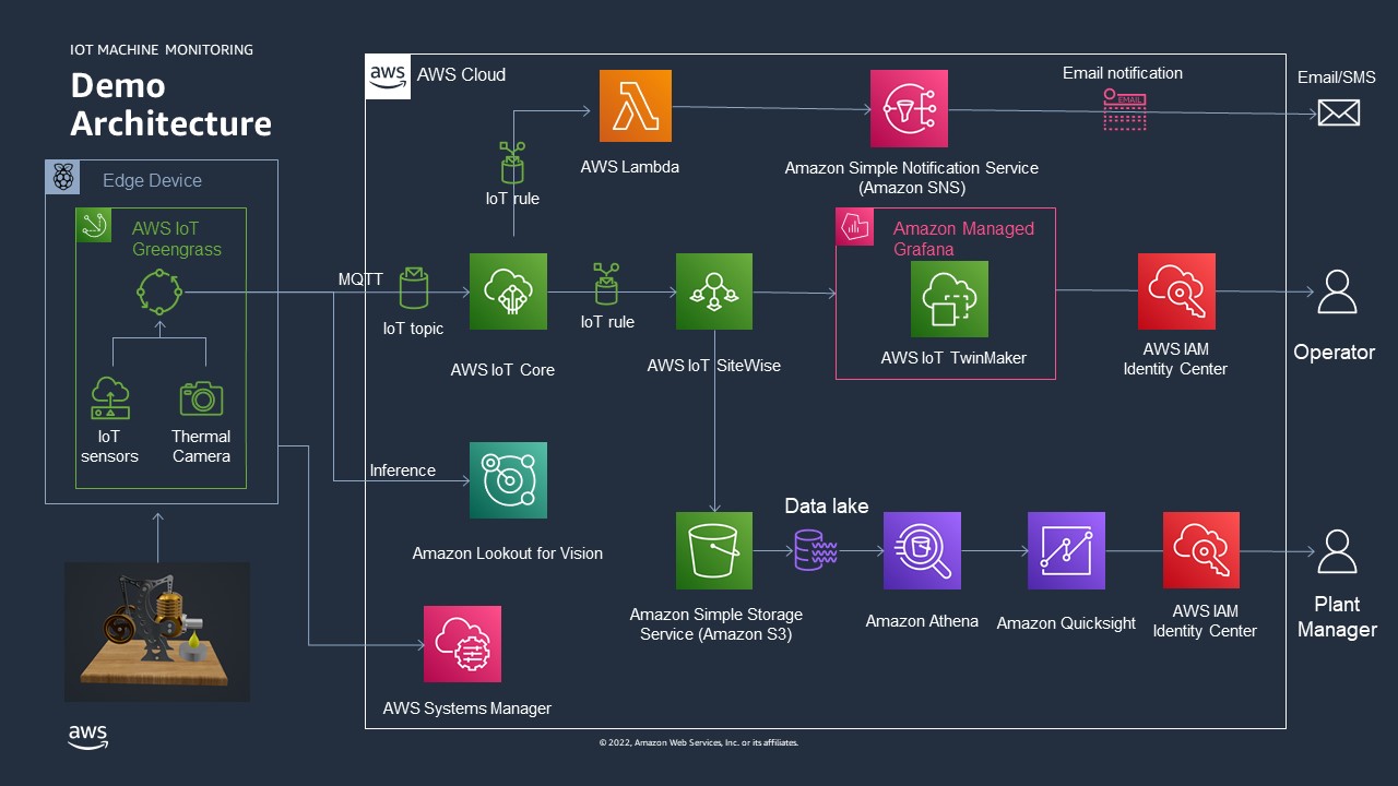
See as well: The AWS Manufacturing Reference Architecture
Other resources
- Check out the German language blog about this demonstration!
- 932 views
AWS services used in this demonstration
AWS services used in this demonstration- AWS IoT Greengrass V2: Management of the edge software
- AWS IoT Core: The AWS services to manage the IoT messages
- AWS IoT Sitewise: Collect, organize, and analyze data from industrial equipment at scale
- Amazon SNS: Fully managed Pub/Sub service for A2A and A2P messaging
- AWS Lambda: Run code without thinking about servers or clusters (used to generate a custom SMS and email text)
- Amazon Managed Grafana: Scalable and secure data visualization for your operational metrics, logs, and traces
- AWS IoT TwinMaker: Optimize operations by easily creating digital twins of real-world systems
- Amazon Lookout for Vision: Spot product defects using computer vision to automate quality inspection
- AWS Systems Manager: Gain operational insights into AWS and on-premises resources (used to managed the Raspberry)
- Amazon QuickSight A serverless BI service
- AWS IAM Identity Center (Successor to AWS Single Sign-On): Centrally manage workforce access to multiple AWS accounts and applications
- 113 views
About us
About us- Martin Drewes (mdrewes@amazon.de)
- Christophe Renard (chrenard@amazon.es)
- Dario Rivera (darior@amazon.com)
- Stefan Schneider (stsch@amazon.de)
We are Partner Solution architects working for AWS.
We work with AWS partners.
This demonstration will be shown at the Re:Invent Builders fair 2022 in Las Vegas. All implementations follow the AWS Manufacturing Reference Architecture. Every service published on this page is however not officially endorsed by AWS. Please contact us, if you plan to go into production with certain components, we work with hardware partners, system integrators and consulting partners which are happy to turn this demonstration into a professional solution.
- 131 views
Building this Demonstration
Building this DemonstrationWIP: Work in progress: I'm rebuilding the demo setup. I'm documenting while I'm rebuilding. Revisit this page by the end of March 2023 for a complete document
- 156 views
BOM: Bill of Material (Hardware)
BOM: Bill of Material (Hardware)WIP: Work in progress: I'm rebuilding the demo setup. I'm documenting while I'm rebuilding. Revisit this page by the end of March 2023 for a complete document
All measurements in metric units!
| Id | Number | Item | Comment |
|---|---|---|---|
| 1 | 4 | Plywood 250x350mm (Bottom, Middle board, Upper board, cover of case, 6mm thick | beech is very robust. The upper board has to carry quite some load |
| 2 | 1 | Plywood 70x40mm,6mm thick, raiser for the burners | Use the leftover from the cut out of the middle board |
| 3 | 8 | wood screws, 3mm x 15mm | to fasten the three boards |
| 4 | 2 | Plywood 238mmx110mmx6mm | the sides of the cover box |
| 5 | 2 | Plywood 350mmx110mmx6mm | the other sides of the cover box |
| 6 | 1 | HB12: Big Powerstation | the Stirling engine. Pick self assembly. The two cylinder model is more robust against wind from the side. The flame may not generate enough heat for the HB10 or HB11 in windy trade show halls. |
| 7 | 1 | Raspberry 4 Model B 8GB starte kit | The |
| 8 | 1 | Case for DIN rail mount | GeekPi sells an enclosure for rail mounting |
| 9 | 1 | Rail for case (DIN TS35) | The rail will need to be shortened |
| 10 | 1 | TRCT500 IR sensor | Pack of 3. |
| 11 | 7 | Round head M4 screws 10 or 12mm |
|
| 12 | 5 | M4 screw nuts |
|
| 13 | 1 | Kit of jumper cables | Female-Female ones are required. Lengths required vary in between 10cm and 30cm |
| 14 | 1 | kit, flat band cables | to reach the physical location of the Raspberry optical camera |
| 15 | 1 | Raspberry Camera Module 3 Wide | wide angle is important here. The autofocus is very helpful. An earlier camera will work as well. They have however a fixed focus which needs to be broken to just for the focus at ~12cm |
| 16 | 1 | MLX90640 | Infrared camera, 55 degrees, with sockets to plugs. Soldering required for models without a plug... |
| 17 | 1 | plug fo MLX90640 | This plug allows to connect the infrared camera to regular breadboard cables |
Disclaimer: This list looks very concise. This is the third revision of the demonstration. The components are known to work. Most components can be replaced by different ones. There are lots of degrees of freedom...
- 105 views
Mechanical Design and Layout
Mechanical Design and LayoutThe mechanical layout follows a number of requirements:
- robustness: The demonstration will be taken to customers and trade shows. It needs to be robust
- It has to fit into hand luaggage
- No part should be damaged
- Cable connection have to be robust and protected against accidental damage
- It has to look a kind of professional, viewers shouldn't be distracted by non relevant parts
- has to meet the skills of the builder
- basic wood processing
- soldering
- 3D printing
- plastic processing (grinding, drilling, cutting)
The layout looks as follows:
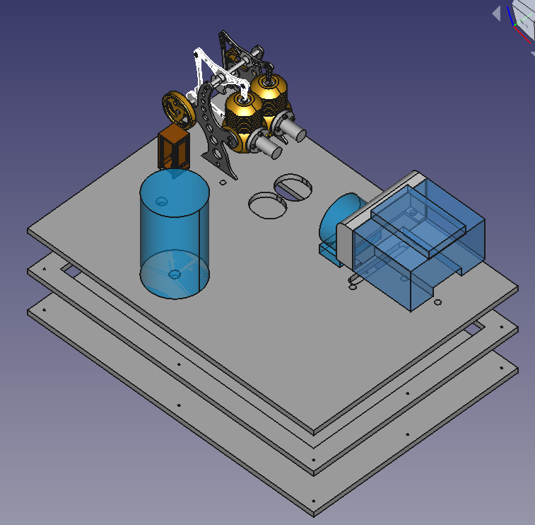
- 122 views
IR Sensor TCRT5000 (RPM Counting)
IR Sensor TCRT5000 (RPM Counting)WIP: Work in progress: I'm rebuilding the demo setup. I'm documenting while I'm rebuilding. Revisit this page by the end of March 2023 for a complete document
Wiring plan.
Sensor seen from the back. Electrical pins at the downside. Pins from left to right. The cable colors are arbitrary, pick them as you like. 30cm long female-female cables work out well. The cables get connected directly with the Raspberry pins, no resistors are required.
| Pin | Meaning | Color | Comment |
|---|---|---|---|
| 1 | A0 | Not being used | |
| 2 | D0 | Red | |
| 3 | GND | Brown | |
| 4 | VCC | Orange |
Placing and Tuning
The sensor has to be placed at about 5mm distance from the flywheel. The flywheel needs a black mark to make the IR sensor to trigger an event.
The TCRT5000 has a potentiometer at the rear side. It allows to calibrate the sensitivity. Turning this potentiometer up to a half turn to the left or right should trigger the events. The TCRT5000 sensor has a LED at the rear side. This sensor will blick with every event when if it is adjusted correctly.
- 62 views
Infrared Camera (MLX90640)
Infrared Camera (MLX90640)We use an infrared camera of the type MLX90460 with a 50mm lens for three purposes:
- temperature cool cylinder
- temperature warm cylinder
- the flame burning
It'll take four components to build this sensor
A Housing for the Sensor (the Rocket)
The camera has to be placed 7 to 10 cm from the flame.
The camera has to have a fixed position in relation to the Stirling engine. The software will have to pick two rectangles out of the image. This is a static software configuration.
The Sensor
The MX90460 with a 50 mm lens It has a 32x24 pixel array. I got it from here.
The connector 3.0V does not get used. The camera gets powered with the VON cable.
Connector to the Camera and extension Cable
The wires to the camera can be directly soldered on. I decided to buy a small plug (4 Pin Dupont female). This cable is 150mm long. This is not long enough to connect it to the Raspberry. I had to put a 300mm long male-female 4 wire extension cable in between. This allows me to change the camera without having to solder. I have to switch colors in the wiring plan to connect to the Raspberry.
The information flow starts from 4 contacts from the camera. I pick it up with with 4Pin Dupont plug. I extend it with a male-female cable. This cable gets connected with the GPIO pins of the Raspberry.
The Wiring Schema
| MLX90460 | Connector Cable Color (arbitrary) | Cable Color (arbitrary) | Raspberry Pin | GPIO |
|---|---|---|---|---|
| VIN | Green | Green | 1 | 3.3V |
| SDA | Purple | Purple | 3 | GPIO 2 |
| SCL | Blue | Blue | 5 | GPIO 3 |
| GND | Yellow | Yellow | 14 | GND |
| 3.0V | - | - | - | - |
Enable the Operating System
The sensor is using the I2C protocol. It needs to be enabled. Use the interactive "Raspberry Pi Configuration" tool and enable it in the "Interfaces" section. Reboot the Raspberry.
An alternative is to update /boot/config.txt with the following two parameters
dtparam=i2c_arm=on
dtparam=i2c_arm_baudrate=1000000
The first parameter will do the same as the interactive tool. The second parameter is a safety precaution to avoid bottlenecks on the bus.
Testing the Sensor
The took i2cdetect needs to be installed upfront:
pi@raspberrypi:~ $ sudo apt-get install -y python3-smbus
pi@raspberrypi:~ $ sudo apt-get install -y i2c-tools
Then use the command
pi@raspberrypi:~ $i2cdetect -y 1
It should list a table. The table has to have an entry "33" somewhere. The is the identifier of an MLX90640 sensor on the bus.
Enabling Greengrass V2 to access the Sensor
The Python scripts run as user ggc_user in Greengrass. Use the following command to allow ggc_user to access i2c:
sudo usermod -a -G i2c ggc_user
Enabling the Calibration of the Camera
The camera will be in different positions depending on the physical setup. The Greengrass component will install a a calibration program as well. This calibration will have to be run as root. The calibration program is written in Python3 and it will need a number of Python libraries. Install them with the command:
At this point, the MLX90640 is ready to be read by the Raspberry Pi. However, since the Adafruit library is being used, a few other libraries need to be installed:
pi@raspberrypi:~ $ sudo pip3 install RPI.GPIO adafruit-blinka
pi@raspberrypi:~ $ sudo pip3 install adafruit-circuitpython-mlx90640
pi@raspberrypi:~ $ sudo pip3 install matplotlib
- 109 views
Optical Camera (Module 3)
Optical Camera (Module 3)WIP...
Cabling is straight forward. The module 3 camera gets connected with a flatland cable. Pass through holes have to be significant larger.
It'll take one change to allow the Greengrass component to access the hardware component.
Execute the following command:
$ sudo usermod -a -G video ggc_user
- 26 views
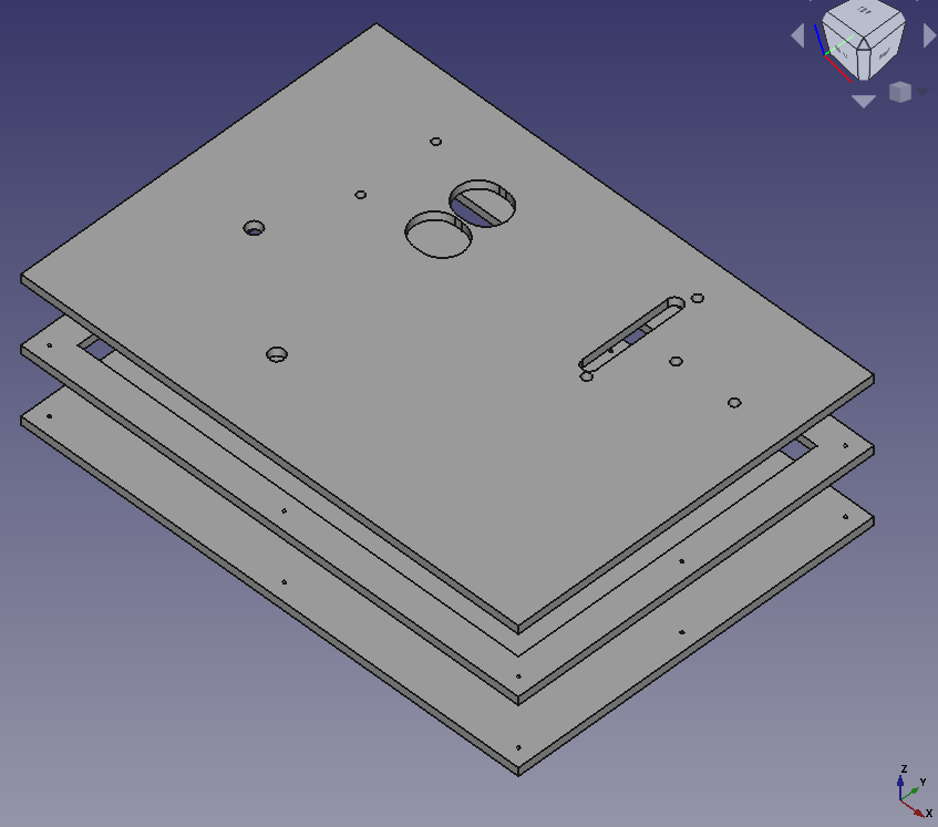
The Base Board
The Base BoardWIP: Work in progress: I'm rebuilding the demo setup. I'm documenting while I'm rebuilding. Revisit this page by the end of March 2023 for a complete document
Use four boards 350mm x 250mm x 6 mm beech plywood boards. The material is very sturdy, it won't bend quickly.
- The lower board is the simplest one. It only needs 8 holes for srews to get tied with the two upper boards
- The middle board has a large cut out which is 20mm smaller than it's size. This empty space will hide all the cables
- Keep a small board at the middle level. The two burners shouldn't sit lower than 6 mm. Make it large enough to fit underneath the two holes for the burner. You can glue it to be in the right position. You can leave it at the right place. The upper and the lower board will keep it in place through friction.
- The upper board is the most complex one. It'll have the holes to fix all the objects and it'll need holes for the cables to go through.
- All components will leave 20mm distance from any boarder. The cover will sit on the upper board. The cover will consist of 10mm walls.
- The cover:
- I used birch plywood boards with the sizes
- 2 boards 350mm x 110mm x 10mm
- 2 boards 330mm x 110mm x 10mm
- The 10mm birch plywood panels allow to use 6mm wooden dowels to connect all 4 boards
- The top cover is the 4th beech plywood board. I nailed it the the side boards
- The cover board isn't shown at the image below
- I used birch plywood boards with the sizes
WIP: The position of the holes will get published at a later point of time. More and more holes are required for the objects which will be documented in future.
- 25 views
The Raspberry
The RaspberryWIP: Work in progress: I'm rebuilding the demo setup. I'm documenting while I'm rebuilding. Revisit this page by the end of March 2023 for a complete document
- 40 views
Raspberry IO Wiring
Raspberry IO WiringWIP: Work in progress: I'm rebuilding the demo setup. I'm documenting it, while I'm rebuilding. Revisit this page by the end of March 2023 for a complete document
The cable colors are arbitrary. Pick which ever color you want to pick!
| Pin | GPIO Id | Cable Color | Connected device | Comment |
|---|---|---|---|---|
| 1 | 3.3V | Red 30cm | MLX90460 Power | Power |
| 2 | +5V | Orange 30cm | TCRT5000 Power | Power |
| 3 | SDA | Blue 30cm | MLX90460 | |
| 4 | +5V | Red | Raspberry fan | Raspberry Cooling |
| 5 | SCL | Yellow 30cm | MLX90460 | |
| 6 | GND | Black | Raspberry fan | Raspberry Cooling |
| 7 | 4 | Red 30cm | TCRT5000 | Binary |
| 8 | 24 | |||
| 9 | GND | Brown 30cm | TCRT5000 | Ground |
| 14 | GND | Broen 30cm | MLX90460 | Ground |
- 89 views
Software Configuration
Software ConfigurationWIP: Work in progress: I'm rebuilding the demo setup. I'm documenting while I'm rebuilding. Revisit this page by the end of March 2023 for a complete document
- 76 views
Raspberry Configuration
Raspberry ConfigurationWIP: Work in progress: I'm rebuilding the demo setup. I'm documenting while I'm rebuilding. Revisit this page by the end of March 2023 for a complete document
OS Configuration
Use the default OS from from Raspberrypi.com and configure it on a 32GB SD card. Use a version with the desktop software. The Raspberry may need to connect to a new Wifi. It's simpler to do this on the fly with a monitor and a key board.
I'm using:
pi@raspberrypi:~ $ more /etc/os-release
PRETTY_NAME="Raspbian GNU/Linux 11 (bullseye)"
NAME="Raspbian GNU/Linux"
VERSION_ID="11"
VERSION="11 (bullseye)"
VERSION_CODENAME=bullseye
ID=raspbian
ID_LIKE=debian
HOME_URL="http://www.raspbian.org/"
SUPPORT_URL="http://www.raspbian.org/RaspbianForums"
BUG_REPORT_URL="http://www.raspbian.org/RaspbianBugs"
I created a user pi for backward compatibility reasons.
Upgrade to the latest packages
$ sudo apt update
$ sudo apt dist-upgrade
$ sudo apt clean
$ sudo reboot
Prepare GreenGrass V2 installation
Install GGV2 accoring to this installation page.
Allow Greengrass user to access GPIO
Execute the following command to make the ggc_user to be part of the gpis group:
$ sudo adduser ggc_user gpio
- 62 views
FAQ: Frequently asked Questions
FAQ: Frequently asked QuestionsHow do I implement this architecture?
All AWS services are public available. The demonstration has been build using public available tutorials. Everything in the AWS cloud can be generated by scripts or configured through the AWS console
I am a AWS customer or partner and I'm interested in the demos and the services. How can I adopt them?
Get in touch with us. We will help you depending on your business case.
Is this architecture ready for industrial production use?
Yes and no...
Yes: all AWS services all highly available. They are scalable. Security is at a production level. The Greengrass V2 container manages the software on the Raspberry at a production level.
No: The Raspberry, the sensors and the wiring is not a professional level. We recommend to work with AWS partners who have verified Greengrass V2 hardware and carrier grade sensors. This project had no funding. This was the cheapest solution.
The quality of the Python scripts which run on the Raspberry are not at a quality level to use it at production. There is very limited error checking; there is very limited checking for incorrect data; the software has no life cycle. The gathering and filtering of data at the edge device would be different with professional hardware and professional sensors
Can we get access to the Python scripts running in Greengrass V2?
Not as of today (November 2023). The scripts have been derived vom AWS tutorials and Raspberry websites. The sensor libraries are open source raspberry libraries.
AWS does not release the scripts as of today since they did not yet pass the reviews to allow AWS to publish them as Open Source. Such a review would require significant resources in AWS. Please talk to us, we want to share the scripts with the community...
Where can I get such a Stirling machine?
Search for Stirling machines at amazon.com!
We bought our machines from Böhm. Böhm ships self assembly and assembled Stirling engines world wide. We picked the engines since they are robust enough for heavy usage. The oldest machine which we use has more than 20h of operation. Böhm ships as well spare parts.
... and yes, they are a kind of affordable. Get one as a Christmas present. The eight year old in yourself deservers it.
- 108 views
Media transfers to EC instances
Media transfers to EC instancesMost users will have to transfer installation media to the targeted EC systems. Copying data to a Bastian host or a jum start server is the straight forward approach. AWS acually allows to simplify this transfer with the help of S3. The idea is
- Copy installation media to a (private) S3 bucket
- Download media to the target systems for the installations
S3 will store the installation media savely for a future use. S3 costs are relatively low. Delete the S3 files after you don't need them anymore. This will help to keep costs at a minimum.
The AWS IAM (Identity and access management) will help you to keep your data private. This requires a few extra steps.
1. Create a S3 Bucket to store your Installation Media
S3 buckets are world wide uniformly accessible. Make sure that you store your media files in the region you work. This saves costs and it expedites the data transfer.
- Become a user with administration rights in your AWS console
- Go to the S3 screen
- Select "Services" (upper left corner)
- Look or search for "S3" and click on this button
- Pick "Buckets" in the left column (most likely already being shown)
- Pick "Create bucket"
- Choose a name (This name will be unique, world wide across AWS!)
- Pick the region in which you work (a remote region will create a bit of costs, increase access latency and it may put your data under a different legislation)
- Do not pick any other option. The default setting will create a user private bucket. The costs will be OK. Access speed will be OK as well. All options, but the region can be changed later on.
- Consider to create some subfolders in your bucket. It's straight forward...
Test the entire setup. The AWS console allows you to up and download files as well
- Use the console to upload a file to a bucket.
- Try accessing the file through it''s URL. This shouldn't work.
- Use the download option to download it again
Background information: You have the authority of the user with whom you logged into the console to perform these operations.
2. Uploading your Media Files
There are a number of options:
- The AWS console. See above
- There are S3 tools out there. Search for them. You will have to provide these tools with a public and a secret user key in order to authenticate the AWS users.
- Use the AWS CLI (Command Line Interface). You will have to provide these tools with a public and a secret user key in order to authenticate the AWS users.
- The AWS CLI needs to be installed on on-premises systems manually.
- Most Linux and Windows AMIs have it preinstalled. Check your EC2 system and install it manually if needed.
3. Downloading the Media Files to the EC2 Systems
Downloads within a region are very fast. We will use the AWS CLI which is preinstalled on most AMIs. Download it here if it is not installed. The EC system will need access to an S3 end point. This is given as long as the system has Internet and DNS access (very common). A in VPC S3 end point is an alternative (unlikely in a new setup).
The AWS CLI allows for save and secure resource access in AWS. The work we will have to do is:
- Create an access policy which allows to work with one given S3 bucket.
- Attach the policy to a role
- Attach the role to the instance.
This will allow any user on the EC2 instance to access the S3 bucket without any extra authenticaten. No IAM user will have to leave the individual credentials on the machine. User on the machine can allow perform a well defined scope of actions.
3.1 Creation of a Bucket Access Policy
Perform the following steps on the AWS console
- Select Services (upper left corner in window)
- Search for "IAM", select it.
- Pick "Policies" from the left column
- Push "Create Policy" button
- Select tabulator "JSON"
- Replace content with the following content:
{
   "Version":"2012-10-17",
   "Statement":[ {
         "Effect":"Allow",
         "Action":[ "s3:ListAllMyBuckets" ],
         "Resource":"arn:aws:s3:::*"
       },
       { "Effect":"Allow",
         "Action":[ "s3:ListBucket", "s3:GetBucketLocation" ],
         "Resource":"arn:aws:s3:::examplebucket"
       },
       { "Effect":"Allow",
         "Action":[ "s3:PutObject",
                    "s3:PutObjectAcl",
                    "s3:GetObject",
                    "s3:GetObjectAcl",
                    "s3:DeleteObject"
                 ],
                 "Resource":"arn:aws:s3:::examplebucket/*"
      }
    ]
 }
Replace the string examplebucket with your individual bucket name. Give it a name. For example "mediaaccess". Save everything.
3.2 Create a Role for EC2 Systems
It'll take a role which we associate with the EC2 systems which need to access the bucket with the installation media.
- Use the console. Use "Services" in the upper left corner
- Search for "IAM" and select it
- Select "Roles" in the left column
- Push "Create Role"
- "AWS service" with EC2 is high lighted
- Click on "Nect: Permissions" in the lower right corner
- Enter the name of your policy ("mediaaccess") in the search field.
- Mark the policy and click on "Nect: Tags"
- Optional: Add a tag
- Click on "Next: Review"in the lower right corner
- Provide a Role name and a description
- Click on "Create Role" in the lower right corner
3.3 Associate the Role with all relevant Instances
The EC2 inszances need to be enabled to act with this role
- Use the console. "Use "Services" in the upper left corner
- Search for "EC2" and select it
- View all instances
- Pick your instance
- Select "Actions" -> "Instance Settings" -> "Attach/Replace IAM Role"
- Select your role in "IAM role"
- Click on "Apply"
There may be two different situations:
- You create a new instance: Consider to assign the IAM role when you create the instance
- Your instance already has a role: Consider to add the policy to the existing role.
4. Downloading media on your Instance
Your instance now has the right to access this bucket without having to add a local user!
Do not add user credentials with "aws configure"!
Run "aws configure" and add the region to be used only. This may have to be done for every Linux user who wants to download media.
You can now download a file install.zip from the bucket examplebucket your media with a command like
$ aws s3 cp s3://examplebucket/install.zip install.zip
The aws s3 sync command is very useful as well. It acts similary to the Linux rsync command.
- 319 views
IP Adress Failover for highly available AWS Services
IP Adress Failover for highly available AWS ServicesAbstract
This documents describes the implementation of high available failover services for applications, which rely on IP address based communication only.
It shows how to configure IP addresses in a Virtual Private Network (VPC), which will route network traffic to a node A or an alternate node B as needed. The document describes how to change the setup of a VPC in case of a failure of node A. The document shows step by step how to automatically assign a service IP address to a standby node B when needed.
The document outlines two different technologies to achieve the same purpose. This allows the implementer to pick the technology that is most suitable for a given infrastructure and the switch over requirements.
Introduction
High available failover architectures are based on a concept where consumers reach a service provider A through a network connection. The core idea is to reroute the consumer traffic to a standby service B when the initial service A fails to provide a given service.
Amazon Web Services provides many building blocks to achieve the purpose to failover network consumers to a new network service. The following solutions are commonly used, they are however not subject of this document:
- AWS Elastic Load Balancers (ELB) in conjunction with AWS Autoscaling allows rerouting traffic to other service providers when needed. AWS Elastic Load Balancers support many other protocols beyond http and https. They may however not work with some proprietary and legacy protocols.
- Domain Name Service (DNS) failover with AWS Route 53 : This approach allows redirecting network consumers which lookup services by name to get redirected to a different network service provider. This concept works well with software solutions, which use name resolution to reach their service provider. Some legacy applications rely however on a communication through IP addresses only.
This paper focuses on network consumers which need to reach a service through a given, fixed IP address.
The two solutions work for any protocol. Both solutions require that a given network consumer can reconnect to the same IP address if the original service hangs and times out.
Amazon Web Services (AWS) offers two solutions to failover IP addresses, which should be chosen, based on the network and high availability requirements.
The first solution is based on the fact that AWS manages IP addresses as separate build blocks with the name “Elastic Network Interface” (ENI). Such an ENI hosts an IP address and it can be attached and detached on the fly from an EC2 instance. This allows redirecting the traffic to such an IP address by detaching and re-attaching ENIs to EC2 instances. The limitation of this concept is that it is limited to a single availability zone (AZ).
An IP address has to be part of a subnet. And a subnet has to be assigned to a given AZ. Attaching the same ENI to instances in two different AZs isn’t possible since a given IP address can belong to one subnet only.
This limitation may not be important for some high availability solutions. There may be however the need to leverage the key features of availability zones by running failover instances in two different availability zones.
The second solution is overcoming this limitation with Overlay IP addresses. AWS allows creating routing tables in a VPC which route any traffic for an IP address to an instance no matter where it is in the VPC. These IP addresses are called Overlay IP addresses.
The Overlay IP address can route traffic to instances in different availability zones. This comes with the challenge that the Overlay IP address has to be an IP address that isn’t part of the VPC. The general routing rules wouldn’t work otherwise.
On premises network consumers like desktops who try to access such an IP address have to be routed to the AWS VPC knowing that the Overlay IP address is not part of the regular subnet of the VPC. This leads to the extra effort to have to route on premises consumers to the AWS VPC with an additional subnet which isn’t part of the VPC itself.
- 7035 views
IP Failover through Reassigning Network Interfaces
IP Failover through Reassigning Network InterfacesThis concept is based on the fact that multiple EC2 instances are reachable through their standard network interface (eth0) and an additional IP address that is used to provide the high available service. The high available service IP address has to belong to a different subnet. This IP address gets modeled with an AWS Elastic Network Interface (ENI). The ENI gets detached from an EC2 instance when the instance fails, it gets then attached to the EC2 instance which is supposed to take a service over.
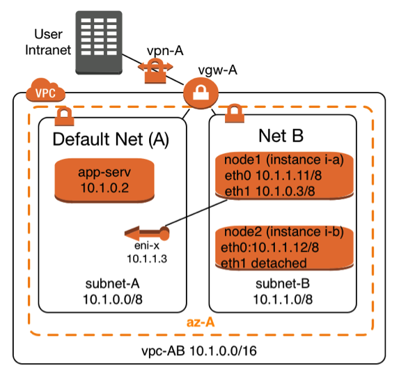 |
The Elastic Network Interface with the name eni-x is currently attached to instance i-a and it can be attached on demand to instance i-b. The highly available service is provided through subnet A. The two service providing instances i-a and i-b can be reached through subnet B with their standard network interfaces (eth0).
This architecture requires at least two subnets:
It takes the following steps to make such a failover scenario work
|
Create and configure an Elastic Network Interface (ENI)
Prerequisites to create an Elastic Network Interface are to have the following information:
- Name of the AWS subnet in which the IP address fits
- IP addresses which matches the CIDR of the AWS subnet
- A security group for the ENI, which allows the required service, protocols to pass. The allowed protocols to pass are typically a subset of the protocols one would use for the primary interface in a non-high-available configuration.
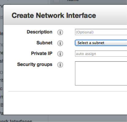 |
The creation can be done manually using the AWS console. You have to choose the EC2 console. Select the entry “Network Interfaces” in the left column. Click on “Create Network Interface” and you’ll see a dialog that looks like the one to the left. |
Enter the required information. The ENI will be created. It’ll have a unique AWS-identifier in the form eni-XYZ,
The alternative is to use the command line with the AWS-CLI tools . The equivalent AWS-CLI command is:
create-network-interface --subnet-id <value>[--description <value>] [--private-ip-address <value>]
Network Configuration for the Linux Instances
Linux instances have to learn that they have to return the network traffic through the new network interface (eth1) once it is attached. It takes a number of instance specific routing changes once the interface gets attached. It’s important to undo these routing changes after the secondary network interface (eth1) gets detached.
The scripts below work for SLES 11 SP3 instances other Linux distributions will need the routing entries to be performed in different network configuration scripts.
/etc/sysconfig/network/scripts/ifup.local.eth1
The script below needs to be adopted by replacing the two following variables, which are printed in bold letters
- DEFAULT-SUBNET-CIDR: This would be 10.1.0.0/8 according to the network diagram above
- DEFAULT-ROUTER: The default router for the default subnet. This would be 10.1.0.1 for the network diagram from above:
#!/bin/bash
if [ "$1" = 'eth1' ]
then
ip route flush table MYHA
ip rule add from DEFAULT-SUBNET-CIDR table MYHA priority 100
ip route add default via DEFAULT-ROUTER dev eth1 table MYHA
fi
This script needs to be executable. A root user will have to perform this command to achieve this:
chmod +x /etc/sysconfig/network/scripts/ifup.local.eth1
/etc/sysconfig/network/scripts/ifdown.local.eth1
The script below needs to be adopted a replacing the variable shown in bold letters
• DEFAULT-SUBNET-CIDR: This would be 10.1.0.0/8 according to the network diagram above
#!/bin/bash
if [ "$1" = 'eth1' ]
        then
        ip route flush table MYHA
        ip rule del from DEFAULT-SUBNET-CIDR table MYHA priority 100 fi
This script needs to be executable. A root user will have to perform this command to achieve this:
chmod +x /etc/sysconfig/network/scripts/ifdown.local.eth1
Linking the Scripts to the right Directories
The scripts above need to be found by the help of soft links which have to be created by a root user the following way:
cd /etc/sysconfig/network/if-down.d
ln –s ../scripts/ifdown.local.eth1 ifdown.local.eth1
cd /etc/sysconfig/network/if-up.d
ln –s ../scripts/ifup.local.eth1 ifup.local.eth1
Adding an additional Routing Table
The scripts from this section will need an additional routing table. This table can be declared with the following command getting executed by a root user:
echo "100 MYHA" >> /etc/iproute2/rt_tables
Policies needed to Detach and Attach ENIs to EC2 Instances
It’s common that two highly available nodes monitor the other one and take action when the monitored node fails. It takes the following policy to enable a node to perform the required AWS configuration change. Attach this policy to all nodes which are supposed to change the network configuration:
{
  "Statement": [
      {
       "Sid": "Stmt1346888659253",
       "Action": [
           "ec2:AttachNetworkInterface",
           "ec2:DescribeInstances",
           "ec2:DescribeInstanceStatus",
           "ec2:DescribeNetworkInterfaces",
           "ec2:DetachNetworkInterface",
           "ec2:DescribeNetworkInterfaceAttribute",
         ],
         "Effect": "Allow",
         "Resource": [
             "*"
         ]
      }
    ]
}
Scripts to detach and reattach an ENI
The script getInterface.sh below is an example of how the AWS-CLI can be used to dynamically attach an Elastic Network Interface. It requires the dynamic IP to be entered as first command line parameter. The second command line parameter is the primary IP address of the system, which will then host the dynamic address.
The script
- Identifies the name of the ENI by using it’s IP address
- it determines the EC2 instance from which the ENI needs to be detached
- it detaches the ENI
- it waits until the operation has completed
- it attaches the ENI to the second system once it’s available
#!/bin/bash
# This scripts detaches as secondary interface from an instance.
# It then attaches the interface to the instance where it has been executed
#
# Command line parameter
#=======================
# First parameter: IP address which needs to be detached and moved to a
# different instance
echo "Move IP adress: $1 to system with primary IP address $2"
INTERFACE=`ec2-describe-network-interfaces | grep $1 | \
awk /NETWORKINTERFACE/'{print $2 }'`
TONODE=`curl -silent http://169.254.169.254/latest/meta-data/instance-id`
echo "move eni: $INTERFACE to instance id: $TONODE "
DETACH=`aws ec2 describe-network-interfaces --network-interface-ids $INTERFACE | \
awk /ATTACHMENT/'{print $3 }'` INTERFACESTATUS=`aws ec2 describe-network-interfaces --network-interface-ids $INTERFACE | \
awk -F"\t" /NETWORKINTERFACE/'{print $10 }'`
echo "$DETACH to be detached. Current interface status is $INTERFACESTATUS"
aws ec2 detach-network-interface --attachment-id $DETACH --force
echo "Command to detach Interface $INTERFACE submitted"
while [ "$INTERFACESTATUS" = 'in-use' ]
do
 echo "Will sleep 1 second"
 sleep 1
 INTERFACESTATUS=`aws ec2 describe-network-interfaces --network-interface-ids $INTERFACE | \
 awk -F"\t" /NETWORKINTERFACE/'{print $10 }'`
Done
echo "Will attach interface $INTERFACE to $TONODE "
aws ec2 attach-network-interface --instance-id $TONODE --network-interface-id $INTERFACE
More Resources
- 10786 views
IP Address Failover within AZ
Thanks for providing such a great resource of knowledge! I'd like to understand - what is the difference between IP Address failover by the method of attaching/re-attaching an ENI (eth1) versus following the private-IP-reassignment approach in the article here: AWS article: Leveraging Multiple IP Addresses for Virtual IP Address Fail-over in 6 Simple Steps
It seems that using private-IP-address-reassignment would not require changes to the Linux instance network config scripts and be a simpler solution? But are there advantages/limitations to consider between the 2 approaches where a=ENI re-assignment, and b=secondary IP address reassignment?
Many thanks for your input!
- Log in to post comments
AWS Infrastructure
Keep in mind that the AWS networking infrastructure needs to know that it will send traffic to a given IP address. I personally prefer "ENI reattach" since the IP address is only once in the routing system. Updating secondary IP addresses may theoretically lead to duplicate IP addresses. I guess it won't matter...
- Log in to post comments
IP Failover with Overlay IP Addresses
IP Failover with Overlay IP AddressesAWS networking allows creating routing entries for routing tables, which direct all traffic for an IP address to an EC2 instance. This concept allows directing the traffic to any instance in a Virtual Private Network (VPC) no matter which subnet it is in and no matter which availability zone (AZ) it is in. Changing this routing entry for the subnets in a given VPC allows redirecting traffic when needed. This concept is known as “IP Overlay” routing in AWS. It is normally being used in a static way for routers and Network Address Translation (NAT) instances. Overlay IP routing can however be used in a dynamic fashion.
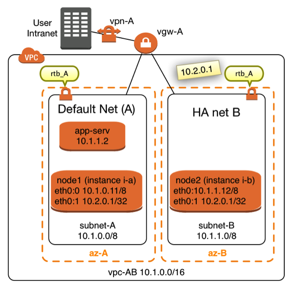 |
The diagram in Figure X shows a network topology in which this concept can get used. Two instances named node1 (EC2 instance i-a) and node2 (EC2 instance i-b) are connected to two different subnets. The two subnets are assigned to the same VPC in two different Availability Zones (AZ). It is not mandatory that both nodes are located in different availalibility zones and subnets, it’s however desirable in many cases. Failover nodes in high availability architectures should be independent of common failure root causes. Both nodes are part of the same Virtual Private Network (VPC). Both subnets share the same routing table named rtb_A. |
The idea is to route traffic from on premises consumers or consumers from within the VPC to the IP address 10.2.0.1 in this case. It’s important that the IP address is outside of the Classless Inter-Domain Routing (CIDR) block of the VPC.
It takes 4 steps to route traffic through an Overlay IP address to EC2 node1 or node2
- Create a routing entry in the routing table which sends the traffic to the EC2 instance in question
- Disable the source/destination check for the network traffic to the two instances in the EC2 network management. The AWS network doesn’t by default send network packets to instances which don’t match the normal routing entries
- Enable the operating system of the EC2 instances to accept these packets
- The two EC2 instances are likely to monitor each other. They are likely to initiate the routing change when needed. The EC2 instances require policies in the IAM roles which authorize them make these changes in the routing table
Creating and managing the routing Entries
The AWS command line interface (AWS-CLI) allows creating such a route with the command:
aws ec2 create-route --route-table-id ROUTE_TABLE --destination-cidr-block CIDR --instance-id INSTANCE
Where as ROUTE_TABLE is the identifier of the routing table which needs to me modified. CIDR is an IP address with the filter. INSTANCE is the node to which the traffic gets directed.
Once the route exists it can be changed whenever traffic is supposed to be routed to a different node with the command:
aws ec2 replace-route --route-table-id ROUTE_TABLE --destination-cidr-block CIDR --instance-id INSTANCE
There are chances if there is a need to delete such a route entry. This happens with the command:
aws ec2 delete-route --route-table-id ROUTE_TABLE --destination-cidr-block CIDR
It may be as well important to check for the current status of the routing table. A routing table can be checked with this command:
aws ec2 describe-route-tables --route-table-ids ROUTE_TABLE
The output will list all routing entries. The user will have to filter out the line with the CIDR in question.
Disable the Source/Destination Check for the Failover Instances
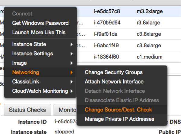 |
The source/destination check can be disabled through the EC2 console. It takes the execution of the following pull down menu in the console for both EC2 instances (see left). The same operation can be performed through scripts using the AWS command line interface (AWS-CLI). The following command needs to be executed one time for both instances, which are supposed to receive traffic from the Overlay IP address: |
ec2-modify-instance-attribute EC2-INSTANCE --source-dest-check false
The system on which this command gets executed needs temporarily a role with the following policy:
{
  "Version": "2012-10-17",
  "Statement": [
    {
      "Sid": "Stmt1424870324000",
      "Effect": "Allow",
      "Action": [ "ec2:ModifyInstanceAttribute"],
      "Resource": [
       "arn:aws:ec2:REGION:ACCOUNT-ID:instance/INSTANCE-A",
       "arn:aws:ec2:REGION:ACCOUNT-ID:instance/INSTANCE-B"
      ]
    }
  ]
}
Replace the individual parameters (bold letters) for the region, the account identifier and the two identifiers for the EC2 instances with the placeholders in bold letters.
Configure the Network Interfaces to receive the Network Traffic of the Overlay IP Address
Linux systems need the overlay IP addresses to be configured as secondary IP address on their standard interface eth0. This can be achieved by the command:
ip address add OVERLAY-IPD/CIDR dev eth0:1
The tools to make the secondary IP address permanent vary across the Linux distributions. Please use the individual documentation to lookup the commands.
Enable the Instances to change the Routes
Switching routes from node to node typically happens in failover cluster. Failover clusters with two nodes monitor each other and take action when the other node doesn’t seem to be alive anymore. The following policy has to be applied to the EC2 instances, which are supposed to monitor each other and be allowed to switch the route when needed:
{
    "Version": "2012-10-17",
    "Statement": [
        {
            "Sid": "Stmt1424870324000",
            "Effect": "Allow",
            "Action": [
                "ec2:DescribeInstances",
                "ec2:DescribeInstanceAttribute",
                "ec2:DescribeTags"
             ],
            "Resource": "*"
        },
        {
            "Sid": "Stmt1424860166260",
            "Action": [
                "ec2:CreateRoute",
                "ec2:DeleteRoute",
                "ec2:DescribeRouteTables",
                "ec2:ReplaceRoute"
            ],
            "Effect": "Allow",
            "Resource": "arn:aws:ec2:region-name:account-id:route-table/rtb-XYZ"
       }
     ]
}
Replace the following variables with the appropriate names:
- region-name : the name of the AWS region
- account-id : The name of the AWS account in which the policy is getting used
- rtb-XYZ : The identifier of the routing table which needs to be updated
- 28202 views
Access the Overlay IP over VPN
Hi,
First I'd like to say, you blog is fantastic. We've implemented SAPHANASR configuration out lined, and the Overlay IP seems to work fine only when working within AWS. (subnet to subnet)
However, we're having issues directing traffic from our main site over a site to site VPN which leverages the AWS VPN Gateway. Was this part successfully implemented? Anything special had to be done on the main site other that implementing a route to the Overlay IP?
I'm asking to know if this is an issue on our side?
Thanks,
Philippe
- Log in to post comments
Limitations of Overlay IP addresses
Yes,
overlay IP addresses can be reached from inside the VPN only.
You will want to run your users like application servers inside the VPN.
You will need a proxy like an ELB/ALB or a SAP GUI router if you want to reach the Overlay IP address from outside of the VPC.
- Log in to post comments
Regarding ELB as a proxy
Hi Stefan,
Thanks for a wonderful explanation.However i am not still able to understand how ELN/ALB will help n forwarding the traffic to the Overlay IP address.Since ELB has no understanding of the OverlayIP address which is plumbed inside the instance and no where mapped in the (just in the route tables).
So how will ELB/ALB will forward traffic to the Overlay IP address.
- Log in to post comments
ELBs/ALBs
Hi,
this page is based on my daily work.
ELBs are great to load balance http and https protocols.
ELBs are great for web facing applications.
I'm working with legacy ERP applications which use lasting TCP connections and my users want to use everything in a VPC and intranet setup.
My GUI users may be idle for more than an hour (see: http://docs.aws.amazon.com/elasticloadbalancing/latest/classic/config-i…).
- Log in to post comments
ELBs for Overlay IP traffic
Hi Stefan
Was there any response for the question asked above?
I'm pasting the question again here -
Thanks for a wonderful explanation.However i am not still able to understand how ELN/ALB will help in forwarding the traffic to the Overlay IP address.Since ELB has no understanding of the OverlayIP address which is plumbed inside the instance and no where mapped in the (just in the route tables).
So how will ELB/ALB will forward traffic to the Overlay IP address.
- Log in to post comments
Answer
An ELB and an Overlay IP address means applying two solutions for one problem. You can use an ELB exclusively. The ELB may end an IP connection after an hour.You will have to make sure that only one target is getting configured at a time. Please touch base with your SAP savy architect from AWS to discuss this problem. There's a lot of innovation at AWS.
- Log in to post comments
This solution has been…
This solution has been created for routers. An EC2 system which acts as a router get packets to an IP range which is out of the VPC routing. It would normally route these packages to a "remote" location.
- You don't need a subnet
- You can narrow down the network mask to one IP only
- The EC2 system is not a router it processes the request.
- The VPC backend knows how to reach the EC2 system, no matter in which AZ
- Log in to post comments
It should be 10.1.0.0/24…
It should be 10.1.0.0/24 and 10.1.1.0/24.
Am I right ?
- Log in to post comments
Will the Overlay IP address sustain a Reboot?
Great documentation!!
I just had one real quick question, will this Overlay IP get relased upon a reboot? Just in case we want to applying monthly paches on these cluster nodes. If yes, what is best way to manage it.
Best,
Stalin
- Log in to post comments
Yes, it'll stay
An overlay IP address is a definition in a routing table. It's not directly elated to the EC2 instance. It'll survive a reboot.
- Log in to post comments
OVERLAY IP
How will i communicate overlay ip, if the overlay ip is from different VPC
- Log in to post comments
It's reachable from inside the VPC
Any IP address within the VPC will be routed to the EC2 instance behind. This happens because they (hopefully) use the same routing table. You may have to maintain multiple routing tables if needed. An overlay IP address can't be reached from outside the VPC. The routing won't work :-( .
- Log in to post comments
Starting Greengrass V1 automatically on a Raspberry Pi
Starting Greengrass V1 automatically on a Raspberry PiGreengrass core on a Raspberry Pi needs to be started manually.
The following script will create a system-D control file and use it to start the service.
The service will then restart automatically at any reboot. Non disclaimer.
Preconditions
- This script with Greengrass V1 only. Greengrass V2 doesn't need it anymore.
- The script has been tested on a Raspberry Pi 4B with Debian. The script will most likely work on all distributions using system-D
- Have Greengrass V1 installed.
Non Disclaimer
- The scripts needs to be executed with elevate super privileges. This is mandatory. It may however created harm to your system. Check the script upfront. There is no warranty.
- The script will delete any old versions of the system-D service file /etc/systemd/system/aws-ggc.service
- The script will need a bash shell and the following commands installed (very likely to be preinstalled):
- echo, systemctl, if
The Installation Script
Create a file with the name installSystemD.sh:
#!/usr/bin/env bash
# version 1.1
# March, 2021
SERVICEFILE="/etc/systemd/system/aws-ggc.service"
if [[ -e ${SERVICEFILE} ]];then
   echo "AWS Greengrass Service is already installed as SYSTEMD, trying to stop
the service."
   echo "*****";
   systemctl stop aws-ggc.service
   rm ${SERVICEFILE}
fi
echo "[Unit]" >  ${SERVICEFILE};
echo "Description=AWS Greengrass Service" >>  ${SERVICEFILE};
echo "After=syslog.target network.target" >>  ${SERVICEFILE};
echo " " >>  ${SERVICEFILE};
echo "[Service]" >>  ${SERVICEFILE};
echo "Type=forking" >>  ${SERVICEFILE};
echo "User=root" >>  ${SERVICEFILE};
echo "WorkingDirectory=/greengrass/ggc/core" >>  ${SERVICEFILE};
echo "ExecStart=/greengrass/ggc/core/greengrassd start" >>  ${SERVICEFILE};
echo "ExecStop=/greengrass/ggc/core/greengrassd stop" >>  ${SERVICEFILE};
echo "Restart=always" >>  ${SERVICEFILE};
echo "RestartSec=60" >>  ${SERVICEFILE};
echo " " >>  ${SERVICEFILE};
echo "[Install]" >>  ${SERVICEFILE};
echo "WantedBy=multi-user.target" >>  ${SERVICEFILE};
systemctl daemon-reload
systemctl enable aws-ggc.service
systemctl start aws-ggc.service
echo "Done installing prerequisites (SYSTEMD)"
Installation of the Service
Make the file executable:
$ chmod u+x installSystemD.sh
Execute the file with super user privileges:
$ sudo ./installSystemD.sh
Check for Success
This command checks whether the service started. It doesn't check whether Greengrass Core is working!
Execute the following command:
pi@raspberrypi:~ $ systemctl status aws-ggc.service
● aws-ggc.service
   Loaded: loaded (/etc/systemd/system/aws-ggc.service; enabled; vendor preset:
   Active: active (running) since Mon 2020-11-23 11:53:08 CET; 30min ago
  Process: 396 ExecStart=/greengrass/ggc/core/greengrassd start (code=exited, st
 Main PID: 452 (5)
    Tasks: 132 (limit: 4915)
   Memory: 236.8M
   CGroup: /system.slice/aws-ggc.service
           ├─ 452 /greengrass/ggc/packages/1.11.0/bin/daemon -core-dir /greengra
           ├─ 634 /lambda/greengrassSystemComponents -runAs=tes
           ├─ 639 /lambda/greengrassSystemComponents -runAs=shadow
           ├─ 647 /lambda/greengrassSystemComponents -runAs=cloudSpooler
           ├─ 665 /lambda/greengrassSystemComponents -runAs=connectionManager
           ├─ 679 /lambda/greengrassSystemComponents -runAs=deviceCertificateMan
           ├─ 692 /lambda/greengrassSystemComponents -runAs=shadowSync
           ├─ 694 /lambda/greengrassSystemComponents -runAs=secretManager
           ├─ 772 /lambda/ipdetector
           ├─ 773 java -cp /lambda/stream_manager/AWSGreengrassStreamManager.jar
           └─1209 python3.7 -u /runtime/python/lambda_runtime.py --handler=green

Nov 23 11:52:54 raspberrypi systemd[1]: Starting aws-ggc.service...
Nov 23 11:52:54 raspberrypi greengrassd[396]: Setting up greengrass daemon
Nov 23 11:52:54 raspberrypi greengrassd[396]: Validating hardlink/softlink prote
Nov 23 11:52:54 raspberrypi greengrassd[396]: Waiting for up to 1m10s for Daemon
Nov 23 11:53:08 raspberrypi greengrassd[396]: Greengrass successfully started wi
Nov 23 11:53:08 raspberrypi systemd[1]: Started aws-ggc.service.
Abort with <ctrl> c
Stopping the Service
$ sudo systemctl stop aws-ggc.service
- 1058 views
DNS Name Failover for Highly Available AWS Services
DNS Name Failover for Highly Available AWS ServicesHighly available AWS services are supposed to be build covering multiple Availability Zones (AZ). Highly available AWS services with single point of failures (example: traditional, non parallel database) need to implement their single point of failure in each Availability and assure that the state of the services stays syncronized.
The second task is to assure that the backup services becomes available to end consumers in the case of a failure of the primary service.
One way to solve this problem is to reassign a given IP adress to the standby server. AWS currently offers two ways to accomplish this failover. The IP Failover scenarios are described here.
This document focuses on a name based failover in a private VPC with access to an on premises intranet.
Targeted architecures for Route53 Failover
This document describes how to switch the IP address for a given name entry in the AWS specific Domain Naming service Route53. This approach will work for the following architectures:
- Consumers of a highly available service connect through the services through name exclusively.
- Consumers of such a service have a comain name service configured which uses the AWS Route52 information
- They use a public AWS IP address with a publicly registered domain
- They have an on premises intranet which uses AWS Route53 as a secondary domain name server.
- End consumers are able to reconnect a network session in a case of failure
The solution presented on the following pages will resonate more with DNS users. A similar solution using Active Directory and the Actice Directory Connector is being presented here.
- 6259 views
Creation of a Route53 Service in a private VPC
Creation of a Route53 Service in a private VPCEnable your VPC to work with Route53. Skip this step if you already use Route53.
The AWS Command Line Interface (CLI) allows to list all VPCs with the following command:
aws ec2 describe-vpcs
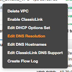 . . |
The following commands will make the instances in your VPC use the domain name entries from Route53. This is most likely required since some of the consumers may be part of the VPC. Use the AWS console. Move to the VPC screen. Make a right mouse click above the VPC which you plan to enable. Select "Edit DNS Resolution" |
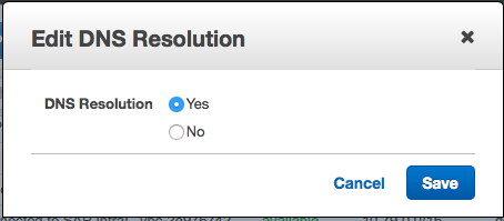 |
It will then show a modal dialog in which you will have to click on "Yes" and "Save" |
The AWS Command Line Interface (CLI) allows to perform this operation though the following command:
aws ec2 modify-vpc-attribute --vpc-id <value> --enable-dns-support
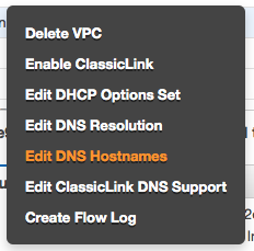 |
The next step happens as well through the AWS VPC console. Hover the mouse above your VPC. Make a mouse right click. Select "" |
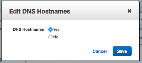 |
It will show a modal dialog. Select "Yes" and Save your data entry. |
The AWS CLI allows to perform this operation though the following command:
aws ec2 modify-vpc-attribute --vpc-id <value> --enable-dns-hostnames
Important: Note down the name of your VPC or tag it. The name will be needed later on.
Creation of the Route53 Hosted Zone (The Domain Name Server)
Use the AWS console. Move to the Route53 screen. Click on the Create Hosted Zone button. You will see a dialog like the following one:
|
|
We assume that you will want to use this domain name server for intranet case only. Fill the fields with the following values:
Save everything through using the Create button. |
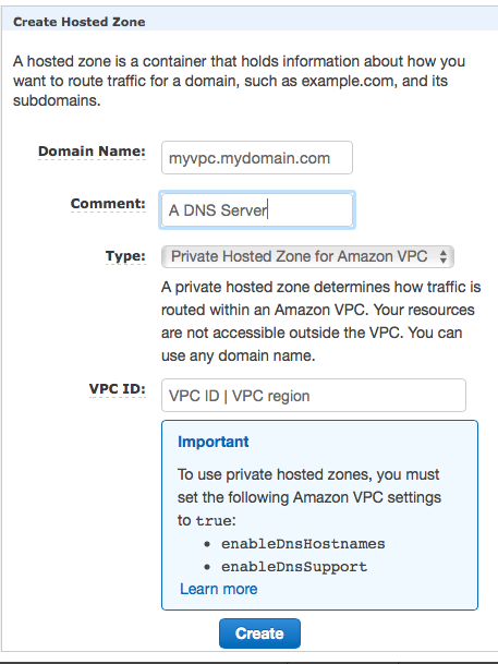
- 2745 views
Changing the IP Address for a Host Name Entry in Route53
Changing the IP Address for a Host Name Entry in Route53The failover can be execute by changing the IP address for a given host name. This means a A record has to be introducted or modified.
This can be done through a CLI command. The information required is:
- Route53 hosted zone id: for example HOSTED-ZONE-ID
- name of entry: for example myservice
- IP address for entry: for example 10.79.252.13
- domain name: for example myvpc.mycompany.com
- Time to life (TTL): for example 10s
Prework
Find your hosted zone through using the AWS console or the AWS CLI command:
aws route53 list-hosted-zones
Create a file like change-resource-record-sets.json:
{
    "Comment": "Update record to reflect new IP address for a system ",
    "Changes": [
        {
            "Action": "UPSERT",
            "ResourceRecordSet": {
                "Name": "myservice.myvpc.mycompany.com",
                "Type": "A",
                "TTL": 10,
                "ResourceRecords": [
                    {
                        "Value": "10.79.252.13"
                    }
                ]
            }
        }
    ]
}
Replace the string myservice.myvpc.mycompany.com with the host name and the domain which matches your requirements.
Replace 10.79.252.13 with the IP address where your service is being provided.
Changing the A record in Route53
Use the following AWS CLI command to implement the change:
aws route53 change-resource-record-sets --hosted-zone-id HOSTED-ZONE-ID --change-batch file:///mypath/change-resource-record-sets.json
Replace HOSTED-ZONE-ID with the identifier for your hosted zone. Pick the correct path to your json configuration file.
This command can be used to create an A record initially. It will work as well if the record already exists. It will then update the IP address and the TTL value.
The command will return a transaction Id which should be caught...
Checking Progess of the Update
The Route53 update takes as while (~20s). The successfull completion of the transaction can be checked with the following command:
aws route53 get-change --id <value>
The result will provide a status field which is PENDING or INSYNC.
- 8787 views
Propagating the Name Change back to the On-Premises Intranet
Propagating the Name Change back to the On-Premises IntranetWe assume here that an on-premises intranet user wants to use a service in the AWS cloud. The service has been made highly available by two services. A high availability service will point to the active and available service by changing the IP address in the Route53 naming service.
| AWS now provides the service Route 53 Resolvers for Hybrid Clouds which solves this problem. |
This page explains what needs to be done to allow on-premises service consumers to get an IP address from am Route53 service. Customers who implemented Microsoft Active Directory will have to follow this blog post. The remainder of this page will deal with DNS implementations.
The problem is, that Route53 is serving only EC2 instances in a VPC. It not exposing it's service back over the VPN tunnel to the intranet.
The solution for this problem are DNS forwarders called "bind forwarders". This page explains how to create such a bind forwarder. Users will actually want to create two bind forwarders in two different availability zones to avoid a single point of failure.
The final architecture will look as follows:
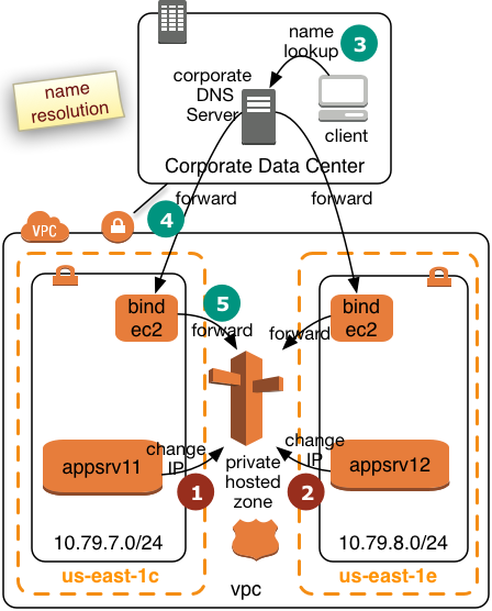 |
We will create two bind forwarders in two AWS Availabilty Zones. Corporate clients will submit their queries to the corporate DNS server. The corporate DNS server will then relay the requests to the bind forwarders. The bind forwarders will query Route53 for the final resolution. We assume the the VPC will operate in a separate subdomain of the intranet. This will simply the routing for the corporate DNS server. The diagram to the left shows how two application servers register or deregister themselves in Route53 win step 1 and 2. Step 3 to 5 shows how the name resolution request will be pulled from Route53. This page describes how a bind forwarder can be configured. We assume that the we have the following network topology:
|
Creation of EC2 Instances
Create two EC instances. The T2 instance type is likely to be sufficient:
- Pick the two IP addresses from above. It'll be important that the subnets are located in different Availability Zones
- Pick Amazon Linux
- Use Security Groups with the following inbound settings
- ssh, tcp, port 22 open to 10.0.0.0/8
- DNS(UDP), port 53 open to 10.0.0.0/8
- DNS(TCP), port 53 open to 10.0.0.0/8
- Use a certificate
- Disk requirements minimal
Configuration of the named Service
The named service is providing the task we need.
Login a ec2-user to the instance and execute the following commands:
sudo yum install bind
Install the packages required for the named services.
Create the file /etc/named.conf. You may use the vi editor:
sudo vi /etc/named.conf
replace the content of this file with this content:
acl goodclients {
   10.0.0.0/8;
   localhost;
   localnets;
};

options {
   directory "/var/named";
   version "not currently available";
   allow-query { goodclients; };
   forwarders {10.79.0.2;};
   forward only;
};

logging{
   channel simple_log {
   file "/var/log/named/bind.log" versions 3 size 5m;
   severity warning;
   print-time yes;
   print-severity yes;
   print-category yes;
   };
   category default{
      simple_log;
   };
   category client{
      simple_log;
   };
};

zone "us-east-1.compute.internal" IN {
   type forward;
   forwarders {10.79.0.2;};
};

zone "awslab.mycompany.corp." IN {
   type forward;
   forwarders {10.79.0.2;};
};
Change all network specific values (bold) with the ones which match your configuration.
Create a log File for named Service
sudo mkdir /var/log/named
sudo touch /var/log/named/bind.log
sudo chmod ug+w bind.log
Start the Service
Execute the command:
sudo service named start
Make the service permanent and have it started after a reboot:
sudo chkconfig named on
Perform this setup for both of your EC2 instances.
- 3243 views
Use the Name Services in the Intranet
Use the Name Services in the IntranetThe final step is to make your name services in the intranet use the bind forwarders.
The intranet DNS servers will have to forward requests for the awslab subdomain to the two bind forwarders.
Individual clients may add the IP addresses of the bind forwarders to their /etc/resolv.conf file.
- 1952 views