Mechanical Design and Layout
Mechanical Design and LayoutThe mechanical layout follows a number of requirements:
- robustness: The demonstration will be taken to customers and trade shows. It needs to be robust
- It has to fit into hand luaggage
- No part should be damaged
- Cable connection have to be robust and protected against accidental damage
- It has to look a kind of professional, viewers shouldn't be distracted by non relevant parts
- has to meet the skills of the builder
- basic wood processing
- soldering
- 3D printing
- plastic processing (grinding, drilling, cutting)
The layout looks as follows:
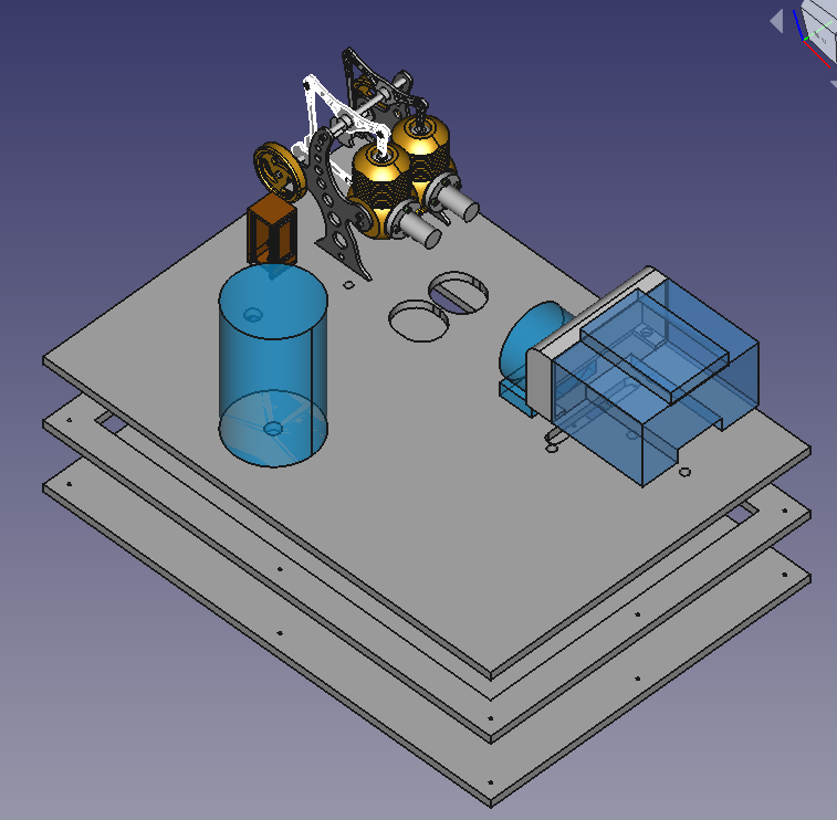
- 122 views
IR Sensor TCRT5000 (RPM Counting)
IR Sensor TCRT5000 (RPM Counting)WIP: Work in progress: I'm rebuilding the demo setup. I'm documenting while I'm rebuilding. Revisit this page by the end of March 2023 for a complete document
Wiring plan.
Sensor seen from the back. Electrical pins at the downside. Pins from left to right. The cable colors are arbitrary, pick them as you like. 30cm long female-female cables work out well. The cables get connected directly with the Raspberry pins, no resistors are required.
| Pin | Meaning | Color | Comment |
|---|---|---|---|
| 1 | A0 | Not being used | |
| 2 | D0 | Red | |
| 3 | GND | Brown | |
| 4 | VCC | Orange |
Placing and Tuning
The sensor has to be placed at about 5mm distance from the flywheel. The flywheel needs a black mark to make the IR sensor to trigger an event.
The TCRT5000 has a potentiometer at the rear side. It allows to calibrate the sensitivity. Turning this potentiometer up to a half turn to the left or right should trigger the events. The TCRT5000 sensor has a LED at the rear side. This sensor will blick with every event when if it is adjusted correctly.
- 62 views
Infrared Camera (MLX90640)
Infrared Camera (MLX90640)We use an infrared camera of the type MLX90460 with a 50mm lens for three purposes:
- temperature cool cylinder
- temperature warm cylinder
- the flame burning
It'll take four components to build this sensor
A Housing for the Sensor (the Rocket)
The camera has to be placed 7 to 10 cm from the flame.
The camera has to have a fixed position in relation to the Stirling engine. The software will have to pick two rectangles out of the image. This is a static software configuration.
The Sensor
The MX90460 with a 50 mm lens It has a 32x24 pixel array. I got it from here.
The connector 3.0V does not get used. The camera gets powered with the VON cable.
Connector to the Camera and extension Cable
The wires to the camera can be directly soldered on. I decided to buy a small plug (4 Pin Dupont female). This cable is 150mm long. This is not long enough to connect it to the Raspberry. I had to put a 300mm long male-female 4 wire extension cable in between. This allows me to change the camera without having to solder. I have to switch colors in the wiring plan to connect to the Raspberry.
The information flow starts from 4 contacts from the camera. I pick it up with with 4Pin Dupont plug. I extend it with a male-female cable. This cable gets connected with the GPIO pins of the Raspberry.
The Wiring Schema
| MLX90460 | Connector Cable Color (arbitrary) | Cable Color (arbitrary) | Raspberry Pin | GPIO |
|---|---|---|---|---|
| VIN | Green | Green | 1 | 3.3V |
| SDA | Purple | Purple | 3 | GPIO 2 |
| SCL | Blue | Blue | 5 | GPIO 3 |
| GND | Yellow | Yellow | 14 | GND |
| 3.0V | - | - | - | - |
Enable the Operating System
The sensor is using the I2C protocol. It needs to be enabled. Use the interactive "Raspberry Pi Configuration" tool and enable it in the "Interfaces" section. Reboot the Raspberry.
An alternative is to update /boot/config.txt with the following two parameters
dtparam=i2c_arm=on
dtparam=i2c_arm_baudrate=1000000
The first parameter will do the same as the interactive tool. The second parameter is a safety precaution to avoid bottlenecks on the bus.
Testing the Sensor
The took i2cdetect needs to be installed upfront:
pi@raspberrypi:~ $ sudo apt-get install -y python3-smbus
pi@raspberrypi:~ $ sudo apt-get install -y i2c-tools
Then use the command
pi@raspberrypi:~ $i2cdetect -y 1
It should list a table. The table has to have an entry "33" somewhere. The is the identifier of an MLX90640 sensor on the bus.
Enabling Greengrass V2 to access the Sensor
The Python scripts run as user ggc_user in Greengrass. Use the following command to allow ggc_user to access i2c:
sudo usermod -a -G i2c ggc_user
Enabling the Calibration of the Camera
The camera will be in different positions depending on the physical setup. The Greengrass component will install a a calibration program as well. This calibration will have to be run as root. The calibration program is written in Python3 and it will need a number of Python libraries. Install them with the command:
At this point, the MLX90640 is ready to be read by the Raspberry Pi. However, since the Adafruit library is being used, a few other libraries need to be installed:
pi@raspberrypi:~ $ sudo pip3 install RPI.GPIO adafruit-blinka
pi@raspberrypi:~ $ sudo pip3 install adafruit-circuitpython-mlx90640
pi@raspberrypi:~ $ sudo pip3 install matplotlib
- 109 views
Optical Camera (Module 3)
Optical Camera (Module 3)WIP...
Cabling is straight forward. The module 3 camera gets connected with a flatland cable. Pass through holes have to be significant larger.
It'll take one change to allow the Greengrass component to access the hardware component.
Execute the following command:
$ sudo usermod -a -G video ggc_user
- 26 views
The Base Board
The Base BoardWIP: Work in progress: I'm rebuilding the demo setup. I'm documenting while I'm rebuilding. Revisit this page by the end of March 2023 for a complete document
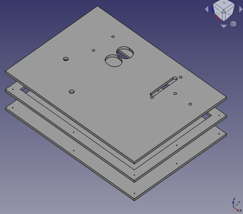
Use four boards 350mm x 250mm x 6 mm beech plywood boards. The material is very sturdy, it won't bend quickly.
- The lower board is the simplest one. It only needs 8 holes for srews to get tied with the two upper boards
- The middle board has a large cut out which is 20mm smaller than it's size. This empty space will hide all the cables
- Keep a small board at the middle level. The two burners shouldn't sit lower than 6 mm. Make it large enough to fit underneath the two holes for the burner. You can glue it to be in the right position. You can leave it at the right place. The upper and the lower board will keep it in place through friction.
- The upper board is the most complex one. It'll have the holes to fix all the objects and it'll need holes for the cables to go through.
- All components will leave 20mm distance from any boarder. The cover will sit on the upper board. The cover will consist of 10mm walls.
- The cover:
- I used birch plywood boards with the sizes
- 2 boards 350mm x 110mm x 10mm
- 2 boards 330mm x 110mm x 10mm
- The 10mm birch plywood panels allow to use 6mm wooden dowels to connect all 4 boards
- The top cover is the 4th beech plywood board. I nailed it the the side boards
- The cover board isn't shown at the image below
- I used birch plywood boards with the sizes
WIP: The position of the holes will get published at a later point of time. More and more holes are required for the objects which will be documented in future.
- 25 views
The Raspberry
The RaspberryWIP: Work in progress: I'm rebuilding the demo setup. I'm documenting while I'm rebuilding. Revisit this page by the end of March 2023 for a complete document
- 40 views